Final Project’s Prototype
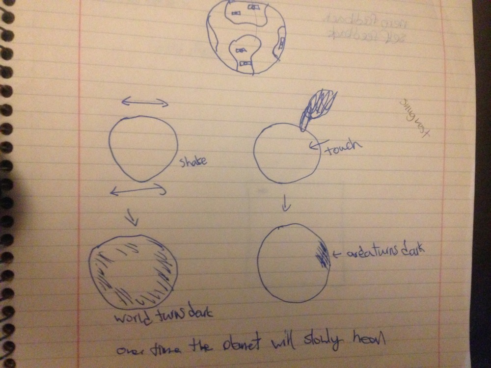
The construction of the Earth
I was able to create a frame Using Craft wires by bending them into pentagons and with a total of 12 sides. The pentagons are taped and divided into the upper and lower half. I wanted to portrait the earth as a fragile ecosystem so I used limited wires for the frame and to fill the pentagons, I used paper from the first project as a symbol of recycling. The earth is made up of 12 pentagons and 6 are blue tissue paper, 2 for the north and south poles and the remainder are for the land. The earth is made by 70% water therefore the most of the area are blue.


For the inside I used another wire frame to support the Arduino and its connections so that it wouldn’t crush the other frame.
")

Testing
For the final project’s prototype I kept the core idea but had to change several components for the original idea. In my original Idea I planned to used several of soft circuits but I had done some research and using capacitive sensor, because I am able to create a better effect and it is also easier to make with pre existing components. During the testing phase, I initially planned for at least 5 capacitive sensors using the available resistors but after further testing, I realized that only 2 of my 5 resistor worked with it and used the rest for the LEDs. I later found that using a external battery would not supply sufficient power to the capacitive sensors therefore it must be plugged in to the computer
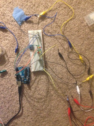
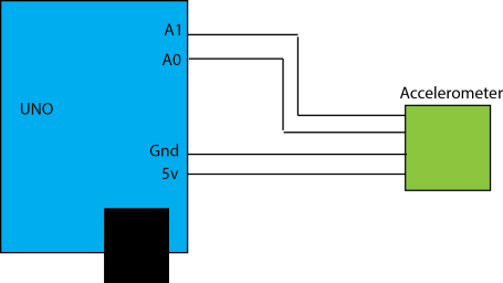
The circuit consists of 2 capacitive sensors, 1 accelerometer 6 coloured LEDs and 3 white Adafruit LEDs. Each capacitive sensor controlled 3 coloured LEDs and the accelerometer controls all the LEDs.
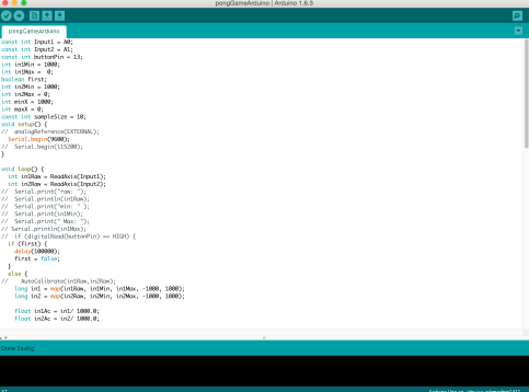
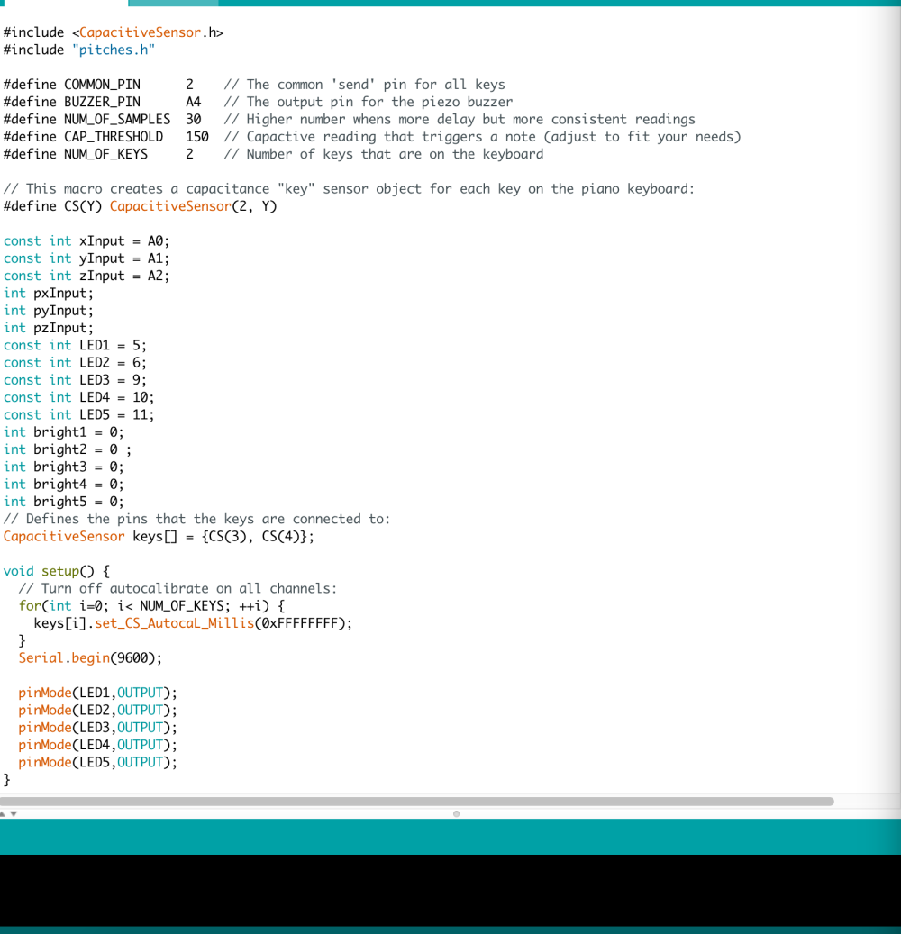
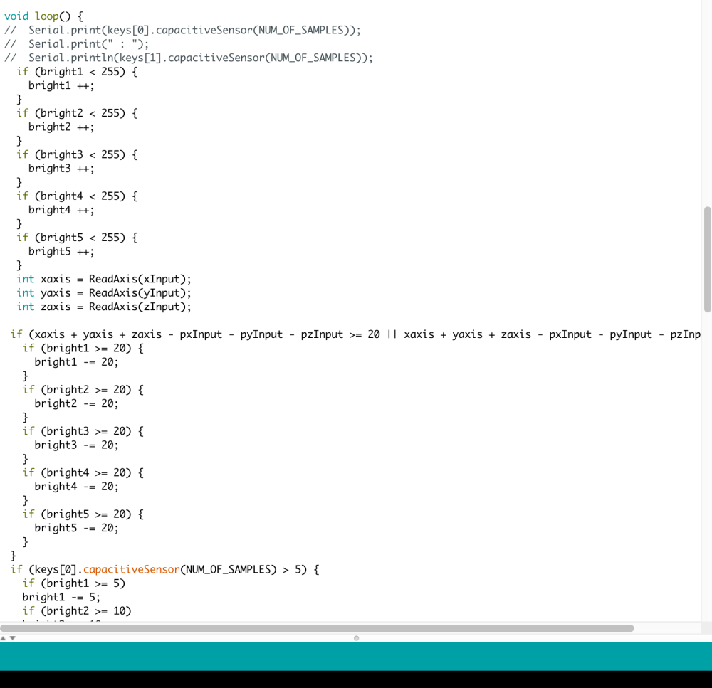
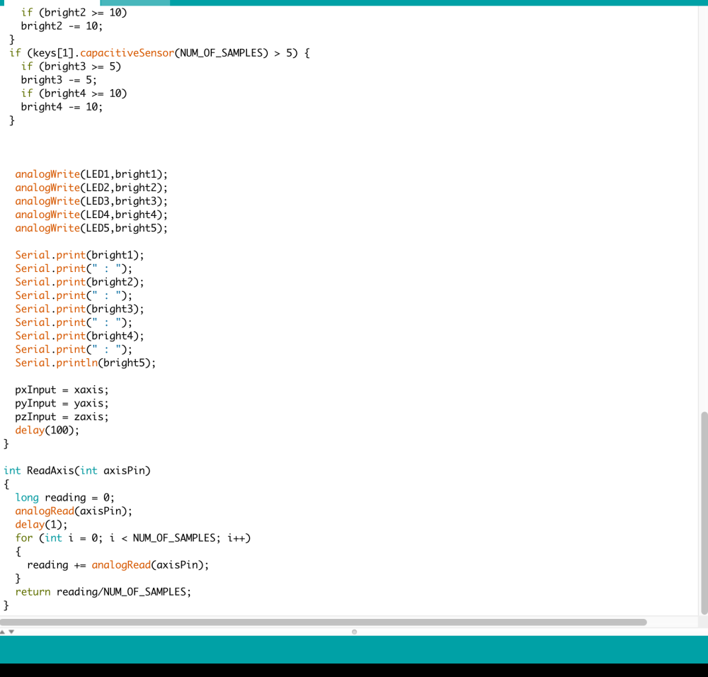
CODE
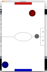
Video